

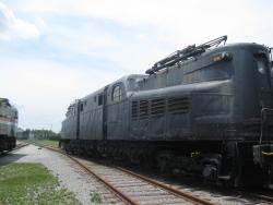
The 4,620-horsepower GG1 was primarily a passenger locomotive, routinely operating at over 100 miles per hour, but was used in freight service as well. Conceived by the Pennsylvania Railroad and built by the Baldwin Locomotive Works and General Electric Company, No. 4800 logged nearly 5 million miles in its forty-five-year life. It was the prototype for a 139-unit fleet built during a decade to serve on the PRR's electrified lines, and the only one with a riveted body shell; the remainder were welded.
USA
YearAdded:
Image Credit: Courtesy Wikipedia/dmb201Image Caption: Penn. RR GG1 Electric Locomotive #4800Era_date_from: 1943
1983
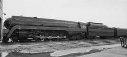
Developed for use in both the plains and mountains, this coal-fired passenger locomotive was among the most advanced in design, construction, and performance of any 4-8-4. Designed by Norfolk & Western engineers and built in the Norfolk & Western Roanoke shops, the 611 was specially balanced to minimize rail damage at high speeds. No. 611, eleventh of fourteen constructed and the last survivor, was retired from service and donated to the Roanoke Transportation Museum in 1959.
YearAdded:
Image Credit: Public Domain (National Park Service)Image Caption: Norfolk & Western #611, Class J Steam LocomotiveEra_date_from: 1941
1984

Maine's heavy snows led turnpike maintenance personnel to bring "left-handed" snow plows into prominence. By using left-handed and traditional right-handed plows in tandem, they were able to distribute snow more evenly - an important advance that has been emulated by many highway maintenance crews across the country.
YearAdded:
Image Credit: Courtesy Flickr/Doug Kerr (CC BY-SA 2.0)Image Caption: Maine TurnpikeEra_date_from: 1947
1999
Society: ASMEMain Category: MechanicalSub Category: Air and Space TransportationEra: 1940-1949DateCreated: 1942Air ZooKalamazooState: MIZip: 49002Country: USAWebsite: http://www.asme.org/about-asme/history/landmarks/topics-a-l/air-and-space-transportation/-238-grumman-wildcat--sto-wing-wing-folding-mecha, https://www.asme.org/getmedia/2d64abc8-3fa3-4d29-92d4-40db4777e8b2/238-Grumman-Wildcat-Sto-Wing-Wing-folding-Mechanism.aspxCreator: Grumman, Leroy
The Wildcat's innovative "Sto-Wing" mechanism developed on the XF4F-4 prototype by Leroy (Roy) Grumman (1895-1982), a founder of Grumman Aircraft Engineering Corporation, was crucial to the U. S. Navy's success during World War II.
The idea of a folding wing was not new: as early as 1920, F.M. Osborne patented a high-wing monoplane with folding wings, but never produced this design. A 1928 plane with folding wings designed by W. Leonard Bonney crashed on its first flight.
YearAdded:
Image Credit: Public Domain (US Navy)Image Caption: Grumman Wildcat “Sto-Wing” Wing-folding MechaEra_date_from: 1942
2006
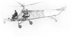
America's first practical helicopter, it pioneered the single main rotor concept that became the predominant helicopter configuration throughout the world. The principles that were developed and demonstrated by the VS-300 had direct application in the design of the early mass-production helicopter, marking the beginning of the world's rotorcraft industry.
The initial flight of the VS-300 was piloted by its designer, Igor I. Sikorsky (1889-1972), on September 14, 1939, in Stratford, Connecticut.
YearAdded:
Image Credit: Courtesy ASMEImage Caption: Sikorsky VS-300 HelicopterEra_date_from: 1939
1984
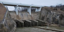
The Miami Conservancy District flood control project was the direct result of the disastrous flood of 1913, when waters from the Miami, Stillwater, and Mad rivers flooded Dayton and surrounding communities in the Miami Valley. More than 400 lives were lost and property damage exceeded $100 million. When Dayton flooded, great fires raged, adding to the devastation. Many believed that the area would never recover.
YearAdded:
Image Credit: Courtesy Flickr/bobosh_t (CC BY-SA 2.0)Image Caption: The Taylorsville Dam, one of the five dry damns to come out of the Miami Conservancy DistrictEra_date_from: 19221972
- Concrete Conduit
- Dry Dam
- Earth-Core
- Flood Control
- Flood Prevention Committee
- Great Depression
- Levee
- Mad River
- Miami Conservancy District
- Miami River
- Retardation Basin
- Stillwater River
- 1920-1929
- 1922
- 1972
- 45424
- ASCE
- Great Dayton Flood
- OH
- USA
- Water Supply & Control
- Civil
- Flood Prevention Committee
- Morgan, Arthur Ernest
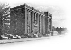
The Connecticut Light & Power Company pioneered the use of pumped storage in the United States at this hydroelectric station. First operated in 1929, the Rocky River Plant had two reversible pumps that somewhat resemble large hydroelectric turbines. This permitted significant improvements in the system efficiency of the company's network of hydroelectric and thermal-electric power generating plants. Water is pumped uphill through a penstock and stored in Lake Candlewood.
YearAdded:
Image Credit: Courtesy ASMEImage Caption: Rocky River Pumped-storage Hydroelectric PlantEra_date_from: 1929
1980
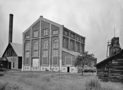
The largest mine hoist in the world, it serves the two incline skipways of Shaft No. 2, almost 9,300 feet long. The overhead winding drum has a diameter of 30 feet, of which the cylindrical center section is 10 feet long. The two 10-foot long end sections taper down to a 15-foot diameter. Wire hoisting ropes (almost 27 tons) could be wound onto a small end of the cylindrical drum as the other rope unwound from the cylindrical section.
YearAdded:
Image Credit: Public DomainImage Caption: Quincy Mine No 2 Hoist House. Two cooling ponds sat alongside the hoist house which served the cross-compound condensed Nordberg engine. After passing through the condenser, hot water went through sprays to be cooled before recycling.Era_date_from: 1920
1984

The 1.6-mile Holland Tunnel was the first underwater vehicular crossing of the Hudson River and the first tunnel specifically designed for automobiles and trucks. It dramatically reduced the time required to traverse the Hudson River, a trip previously possible only by ferry.
A major difficulty when tunneling beneath a river is to keep water and mud from inundating the workers and equipment in the tunnel. Builders of the Holland Tunnel used a shield that enveloped the work site as the excavation progressed; this also avoided obstruction of shipping traffic during construction.
YearAdded:
Image Credit: Courtesy Flickr/Chris Leung (CC BY-SA 2.0)Image Caption: Holland TunnelEra_date_from: 1927
1982
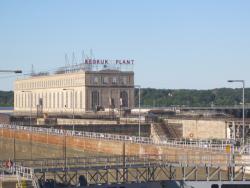
Spearheaded by Hugh Cooper, the Keokuk Dam & Power Plant served as a prototype for many future power plants. The project harnessed the hydropower of the Mississippi River, between Keokuk, Iowa and Hamilton, Illinois.
The crest of the dam is nearly a mile long. The dam structure features 119 arch spans between six-foot-thick piers and a 110-foot-wide pneumatic lock. Combined with the lock, the dam reduced travel time for steamboats by nearly two hours.
YearAdded:
Image Credit: Courtesy Flickr/Michael R. Allen (CC BY 2.0)Image Caption: Mississippi River Lock and Dam number 19Era_date_from: 1913
1988
Innovations