

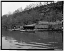
Before the Davis Island Lock & Dam were built, the flow of the Ohio River slowed to little more than a trickle during dry periods. For several months each year, the unreliable flow stranded Pittsburgh's steamboats, towboats, and barges.
The Davis Island Lock & Chanoine Dam experimental project was the first lock and dam ever constructed on the Ohio River. Its achievements also included the first rolling lock gates, the largest movable dam built in the 19th century, and the widest chamber in world history.
USA
YearAdded:
Image Credit: Public Domain (National Park Service)Image Caption: Davis Island Lock and DamEra_date_from: 1885
1985
BBethesdaState: MDZip: 20817Country: USAWebsite: http://www.asme.org/about-asme/history/landmarks/topics-m-z/research-and-development/-197-david-taylor-model-basin-%281939%29Creator: Taylor, David
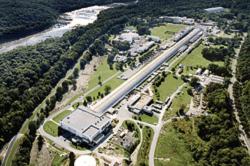
The David Taylor Model Basin is among the largest facilities of its kind in the world, containing a shallow water basin, a deep water basin and a high-speed basin. Using its sophisticated combination of towing carriages, wave makers, and measuring equipment, engineers are able to determine the sea-keeping qualities and propulsion characteristics of ship and craft models up to 40 feet in length. Since it became operational, the facility has provided key support in the development of naval architecture for the Navy, the Coast Guard, the Maritime Administration, and the maritime industry.
YearAdded:
Image Credit: Public Domain (United States Navy)Image Caption: David Taylor Model BasinEra_date_from: 1939
1998
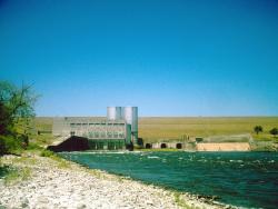
The largest rolled-earth fill dam in the world at the time of its completion, Denison Dam eventually served as a prototype for dam construction in future U.S. Army Corps of Engineers projects throughout the arid plains of the American Southwest. Procedures and equipment developed during its construction are now commonplace in the sampling and testing of soils.
YearAdded:
Image Credit: Courtesy Flickr/Robert Nunnally (CC BY 2.0)Image Caption: Denison DamEra_date_from: 1943
1993
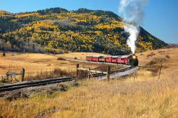
Winding over 64 miles through the majestic San Juan mountains, the narrow-gauge railway known today as the Cumbres and Toltec Scenic Railroad was built as a branch of the extensive Denver and Rio Grande Western Railroad that ran through western Colorado and most of Utah. It originally served the large number of settlers flocking to the gold and silver mines of the region.
YearAdded:
Image Credit: Courtesy Flickr/Larry Lamsa (CC BY 2.0)Image Caption: Cumbres and Toltec Scenic RailwayEra_date_from: 1880
1976
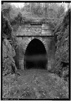
One of four single-track tunnels built by the Blue Ridge Railroad, the 4,273-foot Crozet Tunnel was constructed at a time when hand drills, pickaxes, and black powder amounted to state-of-the-art tunneling technology. At the time of its completion, it was the longest railroad tunnel in the world. Envisioned and built by Claudius Crozet, a French-born educator and civil engineer, the tunnel remains a testament to his belief in advancing rail transportation even when faced with numerous difficulties.
YearAdded:
Image Credit: Public Domain (National Park Service)Image Caption: Crozet's Blue Ridge TunnelEra_date_from: 1858
1976
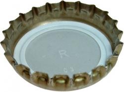
Although bottled carbonated beverages were popular by the 1880s, sealing the bottle was a constant problem. Most "stoppers" were of metal and intended for reuse. None sealed adequately, and contact with the cap often contaminated the drink.
In 1892 (Feb 2), William Painter (1838-1906) patented a cheap, single-use metallic cap, crimped over a lip formed on the bottle neck and lined with a thin cork wafer that both formed a leakproof seal and separated drink and metal.
YearAdded:
Image Credit: Courtesy Wikipedia/KMJ (CC BY-SA 3.0)Image Caption: Crown Cork and Soda Filling MachineEra_date_from: 1892
1994
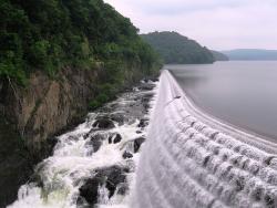
Inferior water and the lack of a sufficient water supply prompted public pressure to find a significant water source for the 360,000 of people living in New York City at the time. Studies determined that the Croton River, 40 miles north of the city, was the best available source. The original system served as a prototype for large-scale water supply projects across America.
YearAdded:
Image Credit: Courtesy Flickr/Otterman56 (CC BY 2.0)Image Caption: Croton Water Supply SystemEra_date_from: 1842
1975
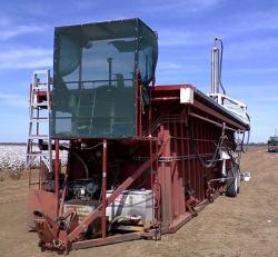
Cotton was once transported from farms to gins by wagons, trucks or trailers. Long waits to unload at the gin stalled harvests until haulers could return to the fields.
Professor Lambert Wilkes of the Department of Agricultural Engineering, Texas A&M University, developed the Cotton Module Builder between 1971 and 1974 with the support of J.K. (Farmer) Jones of Cotton Incorporated. The modules created by the Cotton Module Builder withstood weather, and after transport, the cotton could be easily fed into the gin. Dr.
YearAdded:
Image Credit: Photo by Beaver (Thomas John Macartney)Image Caption: The cotton module builder revolutionized the cotton industry.Era_date_from: 1971
2002
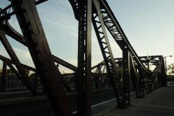
In 1899, engineers from the City of Chicago's Division of Bridges and Viaducts performed a survey of moveable bridge design in the U.S. and Europe. Their study led to the conclusion that the unusual trunnion bascule design would best meet their needs.
YearAdded:
Image Credit: Courtesy Flickr/Matthew Black (CC BY-SA 2.0)Image Caption: Cortland Street DrawbridgeEra_date_from: 1902
1981
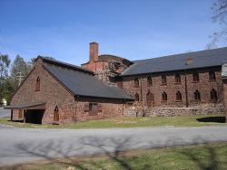
When erected by Peter Grubb to smelt the rich iron ore of the nearby Cornwall ore banks, this stone-built blast furnace was typical for its time, producing about 20 tons of pig-iron and cast-iron products a week. A major reconstruction in 1856 to 1857 produced important changes: the furnace itself was enlarged; the blast-air bellows were replaced by a pair of wooden cylinder "blowing tubs"; the waterwheel that had powered them was replaced by a 20-horsepower steam engine; and a pair of waste-heat boilers to supply the engine was built into the open stack of the furnace.
YearAdded:
Image Credit: Courtesy Wikipedia/Wherring (CC BY-SA 3.0)Image Caption: Cornwall Iron FurnaceEra_date_from: 1742
1985
Innovations